Document
Knowledge Base
The PCIe Gen5 GPU solution revolutionizes the field of generative AI, satisfying the escalating demands by enabling the independent deployment of GPUs at a larger scale. Achieved through a composable architecture and the innovative approach of composable disaggregation, this solution significantly impacts data-intensive tasks. It enhances transfer speeds and overall performance while isolating GPUs from the server while providing flexibility and scalability. The simplified hardware management in independent GPU expansion further contributes to cost savings. Overall, the PCIe Gen5 GPU solution meets the substantial GPU demands in generative AI, delivering enhanced performance, flexibility, and cost-effectiveness.
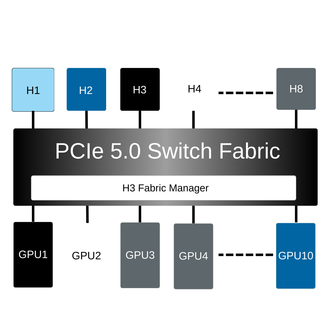
Revolutionizing system dynamics, Falcon 5012 introduces advanced GPU management, enabling up to 8 hosts to dynamically share 10 devices on demand. This streamlines resource allocation, saving significant setup time. The solution allows seamless removal and addition of GPU resources between hosts, ensuring intelligent rearrangement. IT administrators benefit from the cohesive hardware and software solution, focusing more on gaining insights and less on component management. Falcon 5012 makes your workflow more efficient and effective.
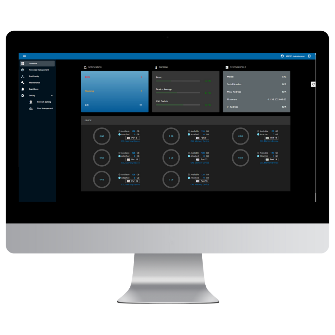
Falcon 5012 ensures optimal system performance through strategic resource management. Actively monitoring GPU health, real-time performance, and errors in both host and device ports facilitates quick issue identification and resolution for stable operation. Introducing flexible switch cascade topologies and configurable host virtual trees enhances resource management flexibility. The solution also provides intuitive resource allocation insights through the Host and GPU views, enabling intelligent resource deployment.
| Features |
|
|---|---|
| Management Interface | Redfish®, RESTful API, GUI |
| System Management |
|
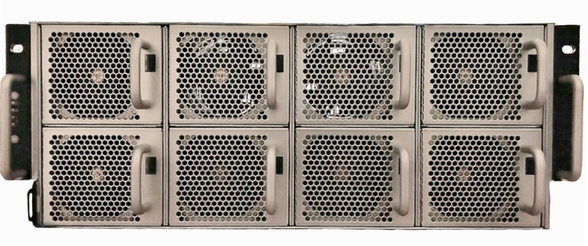
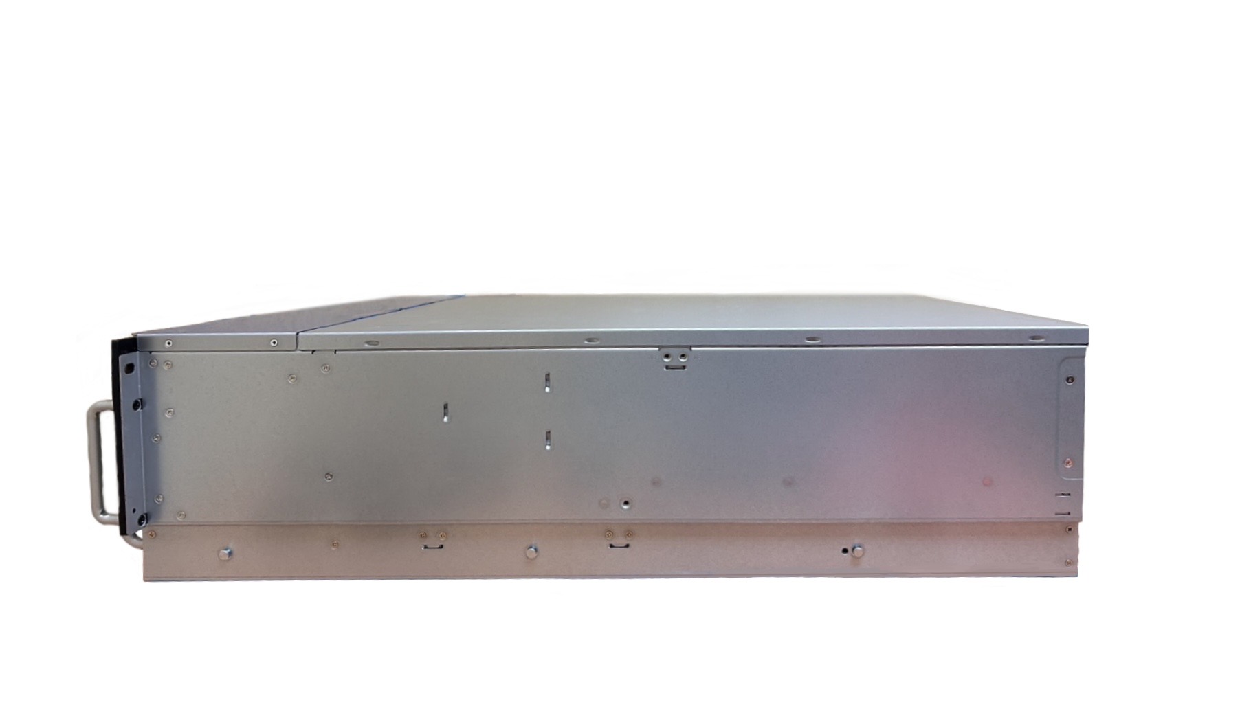
| Model Name | Falcon 5012 |
|---|---|
| BMC | AST 2500 |
| mCPU | Intel ATOM X86 CPU |
| PCIe Switch | Broadcom PEX 89144 PCIe 5.0 switch |
| Device |
GPU, FPGA, network card, and other standard PCIe device (add-in card) Dual-slot width and 10.5” length Supports up to 600W GPU |
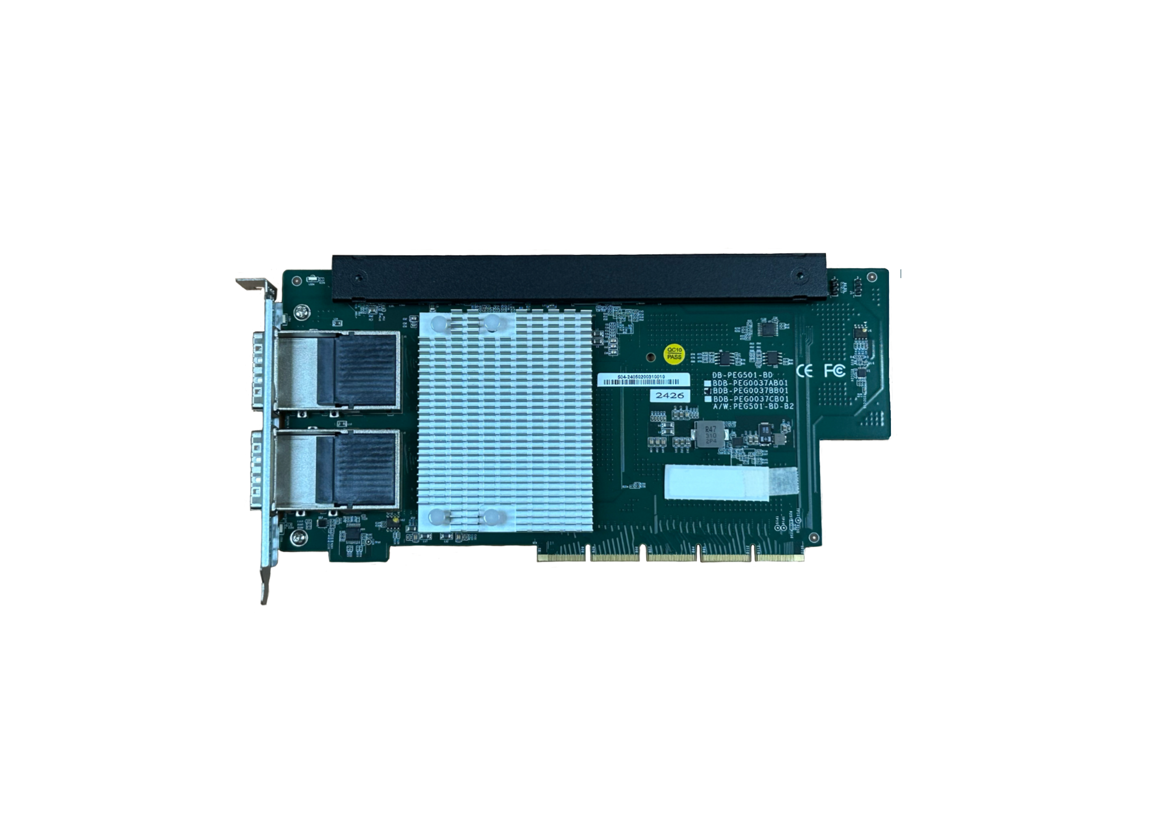
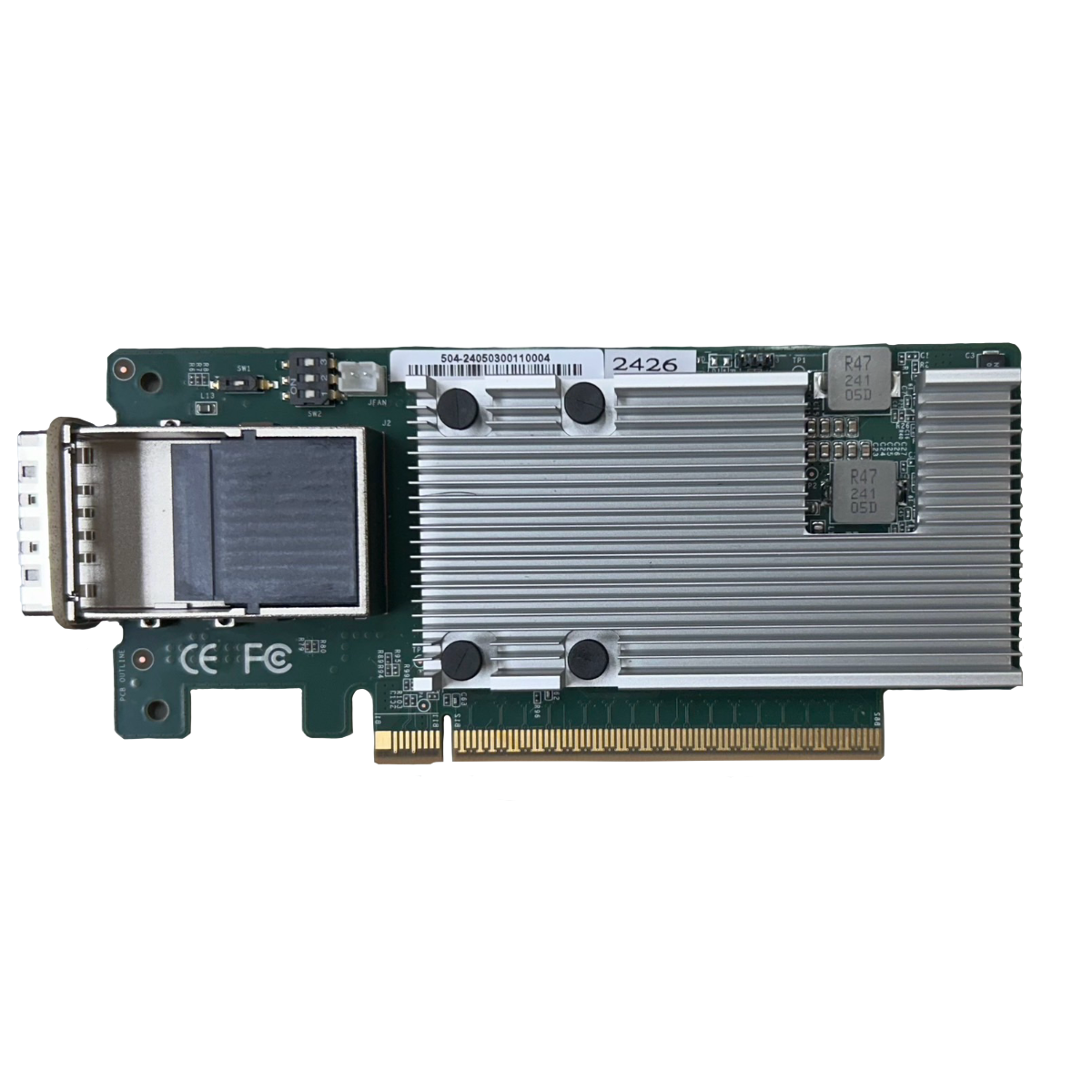
| Host Interface - Standard mode |
|
| Host Interface - Advanced mode |
|
| Operating temperature | 10 degrees Celsius ~ 35 degrees Celsius (50 degrees Fahrenheit ~ 95 degrees Fahrenheit) |
| Ethernet Ports |
|
| Power | Four (4) pieces 2100W or 3200W (2+2 or 3+1 redundant), back removable, hot-swap |
| Fan |
|
| Dimension |
|
| Accelerator |
|
|---|
The Falcon 5012 supports two scenarios: 10 GPUs or 8 GPUs + 4 Network cards, configurable in Standard Mode or Advanced Mode. Advanced Mode, requiring a Premium License, enables flexible, high-performance deployments.
| Application scenarios | Standard Mode | Advanced Mode |
| 10 GPUs | a. 2 Hosts + 10 GPUs | b. 4 Hosts + 10 GPUs |
| c. 6 Hosts + 8 GPUs |
| Application scenarios | Standard Mode | Advanced Mode |
| 8 GPUs + 4 Network cards | d. 2 Hosts + 8 GPUs + 4 Network cards | e. 4 Hosts + 8 GPUs + 4 Network cards |
| f. 6 Hosts + 8 GPUs + 2 Network cards | ||
| g. 8 Hosts + 8 GPUs |
| Configuration | Chassis-wide configuration | Per-switch configuration |
| Host port + Device port | 2 Hosts + 10 GPUs | 1 Host + 5 GPUs |
In the 10 GPUs scenario, each host can independently access the GPUs connected to its switch under Standard Mode.
Figure 1. Block diagram of Standard Mode architecture topology with 2 x16 hosts and 10 GPUs
In the 10 GPUs application scenario under Advanced Mode, two configurations are available.
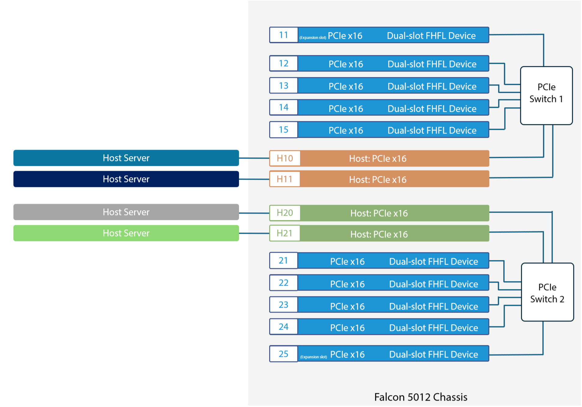
| Configuration | Chassis-wide configuration | Per-switch configuration |
| Host port + Device port | 4 Hosts + 10 GPUs | 2 Hosts + 5 GPUs |
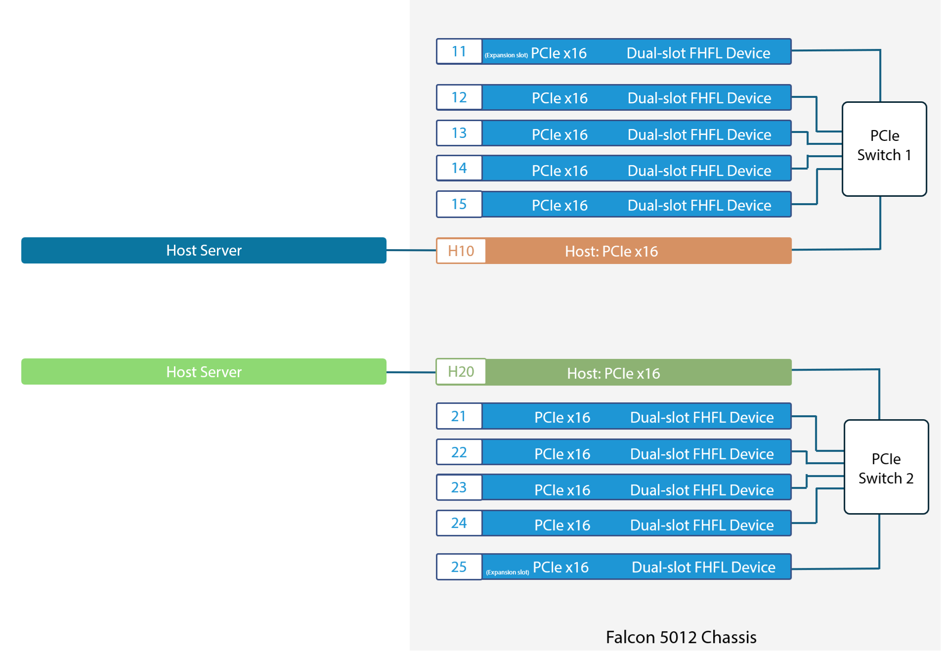
In Advanced Mode, each switch supports 2 hosts and 5 FHFL devices. With 2 switches, the system can connect 4 hosts and 10 FHFL devices.
Figure 2: Block diagram of Standard Mode architecture topology with 4 x16 hosts and 10 GPUs
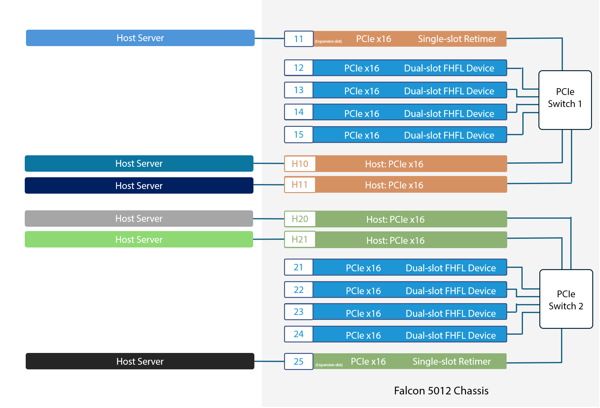
| Configuration | Chassis-wide configuration | Per-switch configuration |
| Host port + Device port | 6 Hosts + 8 GPUs | 3 Hosts + 4 GPUs |
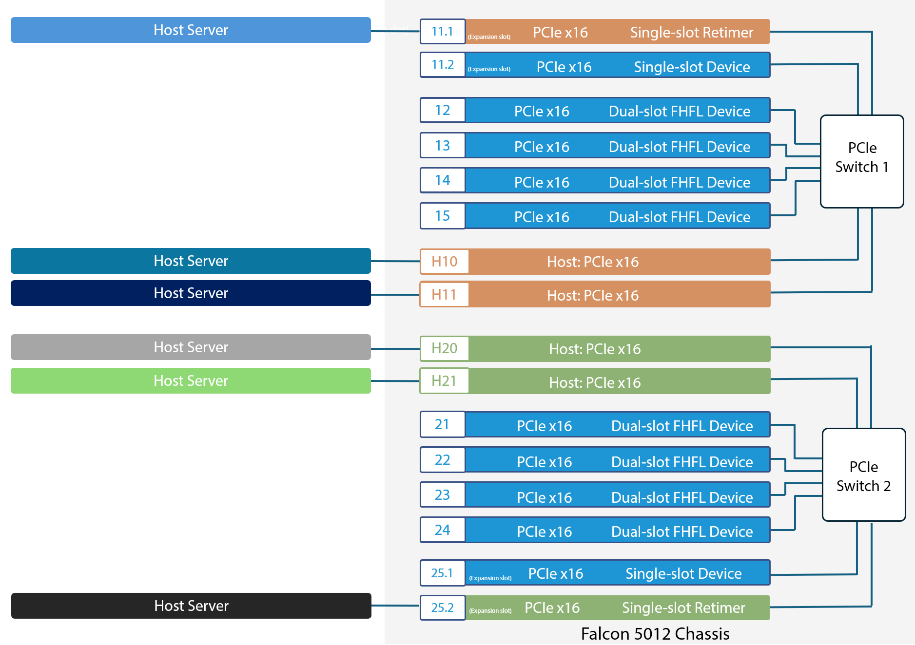
External expansion slots can be connected to retimers to support additional hosts. In this configuration, each switch supports 3 hosts and 4 FHFL devices, allowing 2 switches to connect a total of 6 hosts and 8 FHFL devices.
Figure 3. Block diagram of Advanced Mode architecture topology with 6 x16 hosts and 8 GPUs
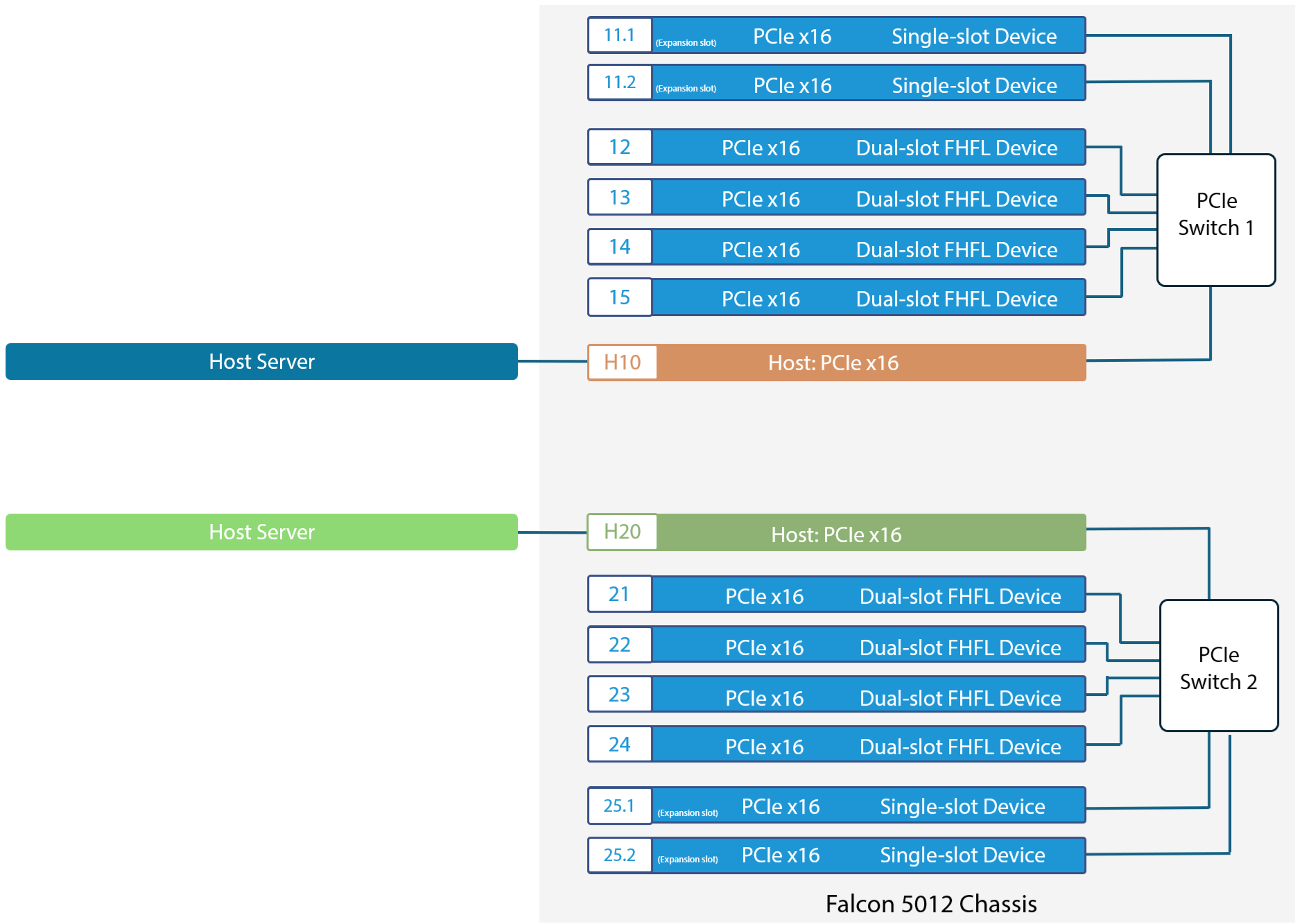
| Configuration | Chassis-wide configuration | Per-switch configuration |
| Host port + Device port | 2 Hosts + 8 GPUs + 4 Network cards | 1 Host + 4 GPUs + 2 Network cards |
In the 8 GPUs + 4 Network cards scenario under Standard Mode, each host can independently access 4 GPUs and 2 Network cards on its connected switch.
Figure 4. Block diagram of Standard Mode architecture topology with 2 x16 hosts and 8 GPUs + 4 NICs
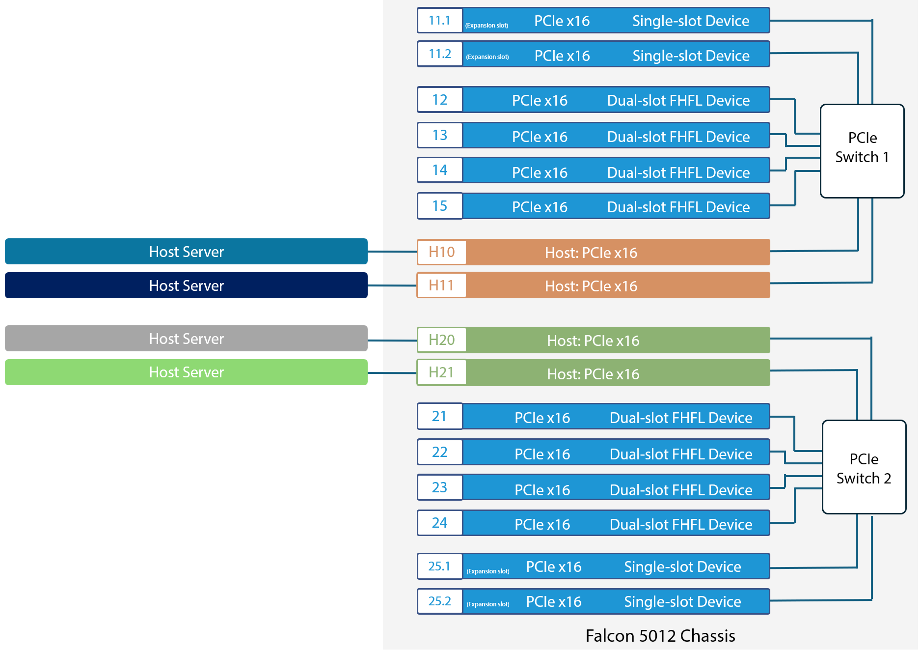
| Configuration | Chassis-wide configuration | Per-switch configuration |
| Host port + Device port | 4 Hosts + 8 GPUs + 4 Network cards | 2 Hosts + 4 GPUs + 2 Network cards |
In Advanced Mode, each switch at least supports 2 hosts, 4 FHFL devices, and 2 single-slot devices, enabling the system to connect 4 hosts, 8 GPUs, and 4 Network cards.
Figure 5. Block diagram of Advanced Mode architecture topology with 4 x16 hosts and 8 GPUs + 4 NICs
| Configuration | Chassis-wide configuration | Per-switch configuration |
| Host port + Device port | 6 Hosts + 8 GPUs + 2 Network cards | 3 Hosts + 4 GPUs + 1 Network card |
Users can designate one of the external expansion slots to connect additional hosts. In this configuration, each switch supports 3 hosts, 4 FHFL devices, and 1 NIC, enabling the chassis to support a total of 6 hosts, 8 FHFL devices, and 2 single-width devices.
Figure 6. Block diagram of Advanced Mode architecture topology with 6 x16 hosts and 8 GPUs + 2 NICs
| Configuration | Chassis-wide configuration | Per-switch configuration |
| Host port + Device port | 8 Hosts + 8 GPUs | 4 Hosts + 4 GPUs |
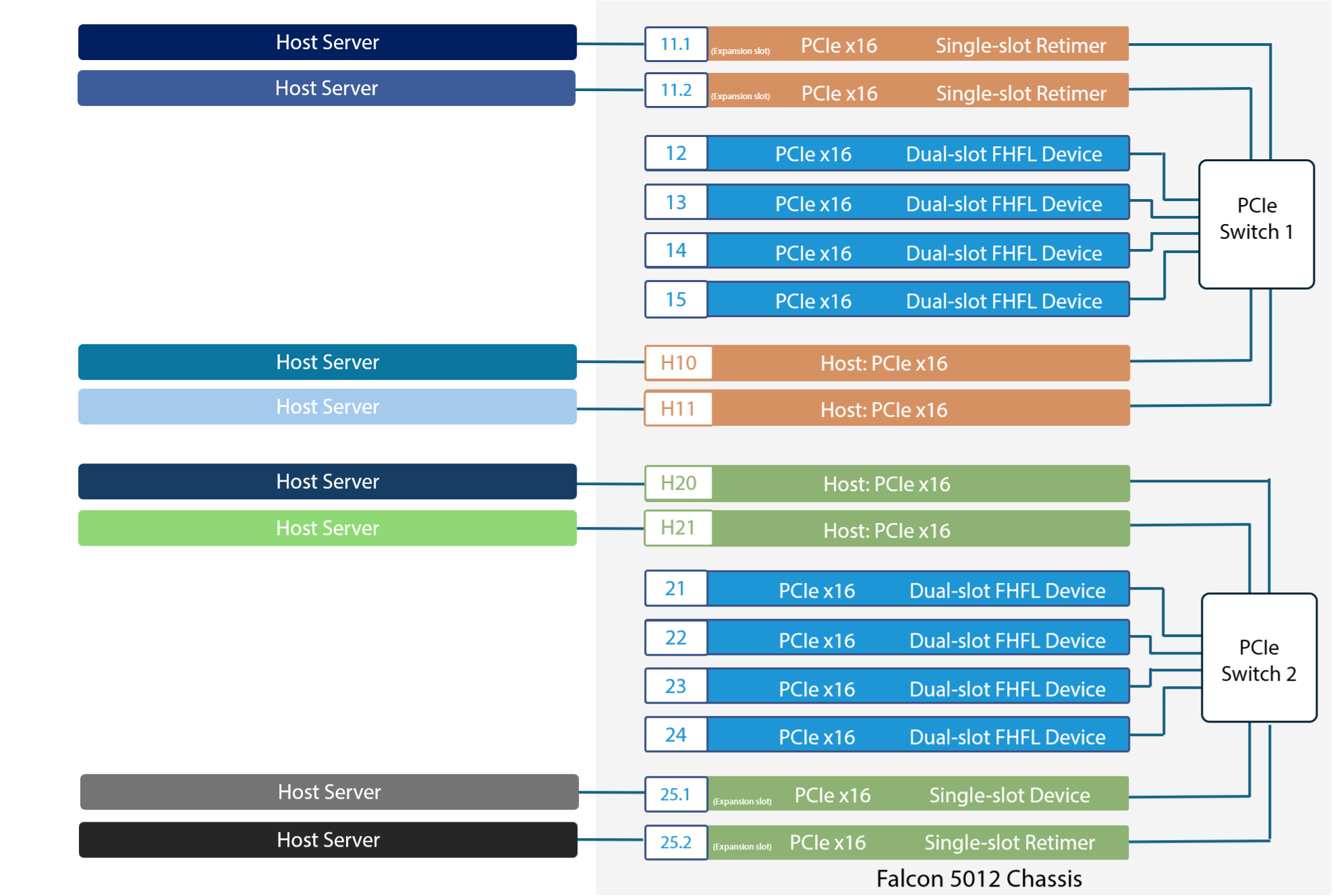
Users can designate external expansion slots to connect additional hosts. In this configuration, each switch supports 4 hosts, and 4 FHFL devices, enabling the chassis to support a total of 8 hosts, and 8 FHFL devices.
Figure 7. Block diagram of Advanced Mode architecture topology with 8 x16 hosts and 8 GPUs
For more information, please contact sales@h3platform.com for license purchase.
If you want to apply for any product display, please write a form and we will contact you after receiving the message.