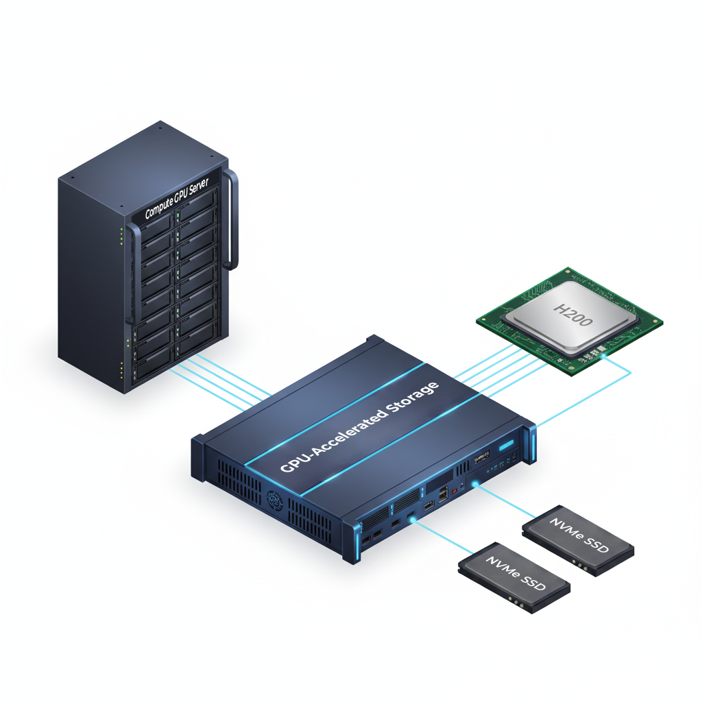
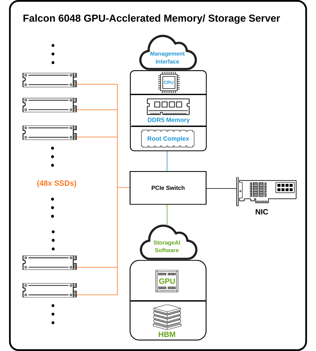
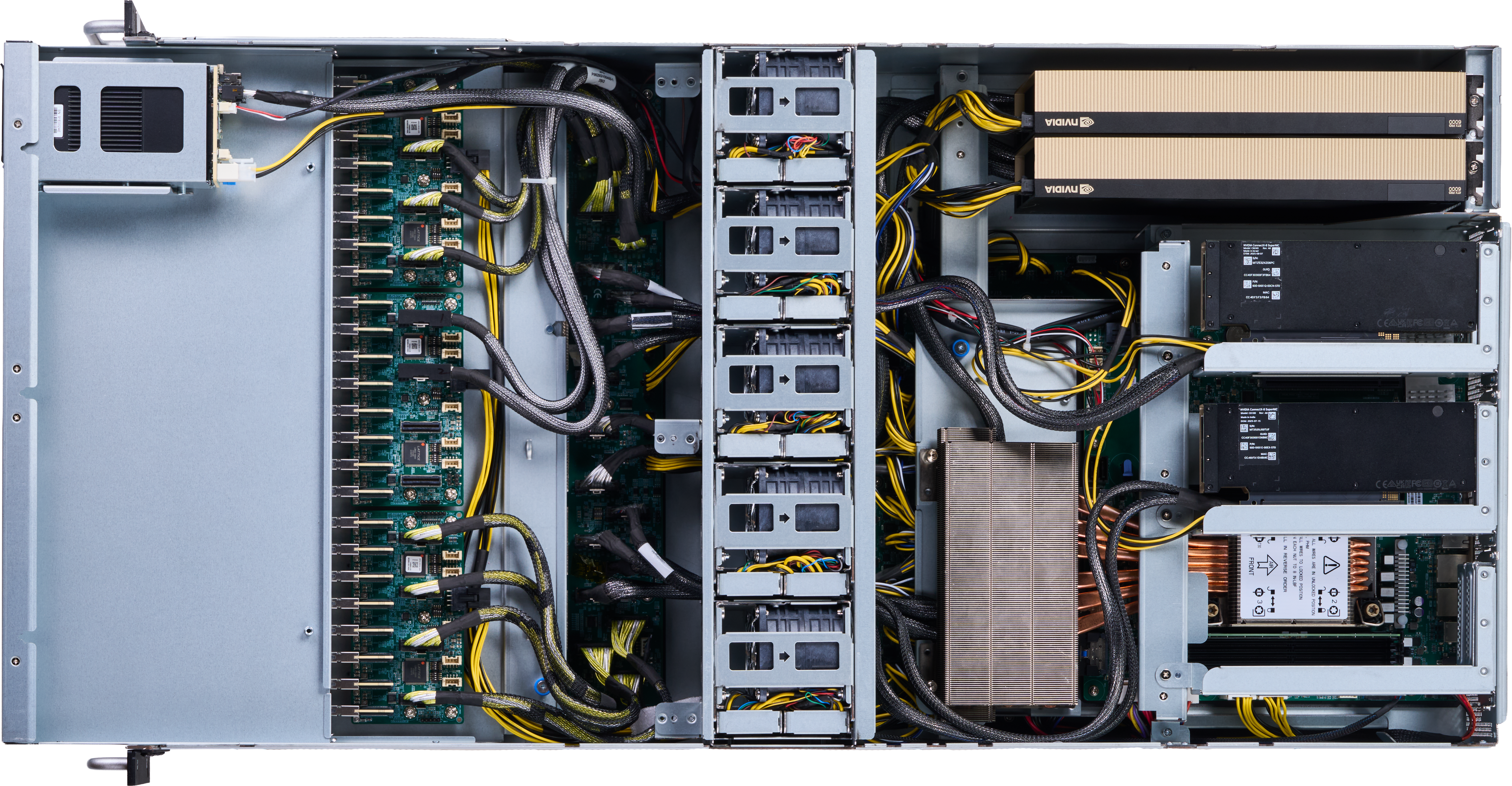
Falcon 6048 features a GPU-accelerated storage architecture and software services that provide storage-class memory capacity to compute GPUs running data-intensive AI applications. When an application’s memory requirement exceeds the GPU’s memory capacity, the data is remapped and accesses are redirected to the NVMe SSD via RDMA-based communication between the compute GPU and the storage service GPU. Falcon’s PCIe Gen6 fabric, GPUs, NVMe SSD’s and NICs work seamlessly together to support ultra-high-throughput, low-latency access to peta-scale data and high GPU utilization for AI applications running on compute node GPUs.
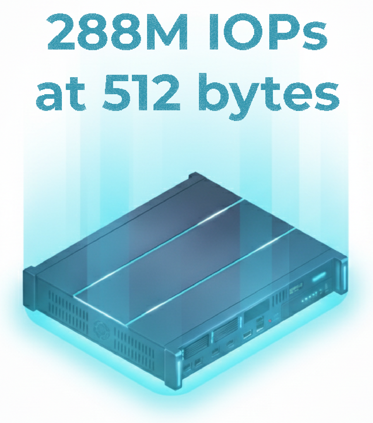
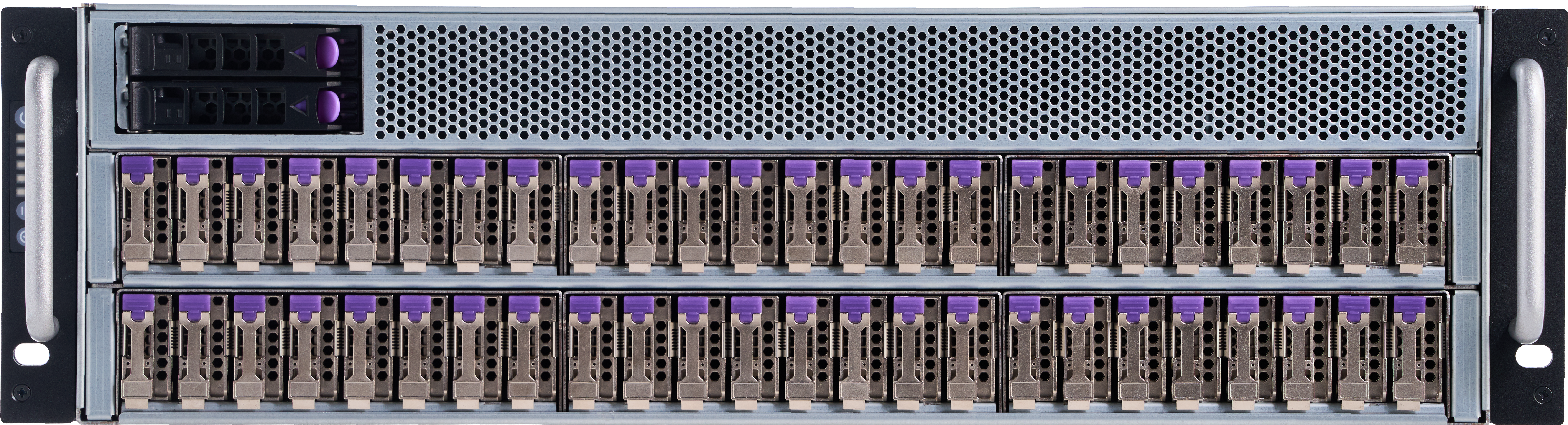
Powered by 2 Broadcom PCIe Gen6 switches and 48 E1.S NVMe SSDs, Falcon 6048 achieves up to 288 million IOPS, delivering ultra-low latency and massive parallel throughput ideal for AI training and large-scale data analytics. (Tested with H100 GPUs and CX8 NICs)
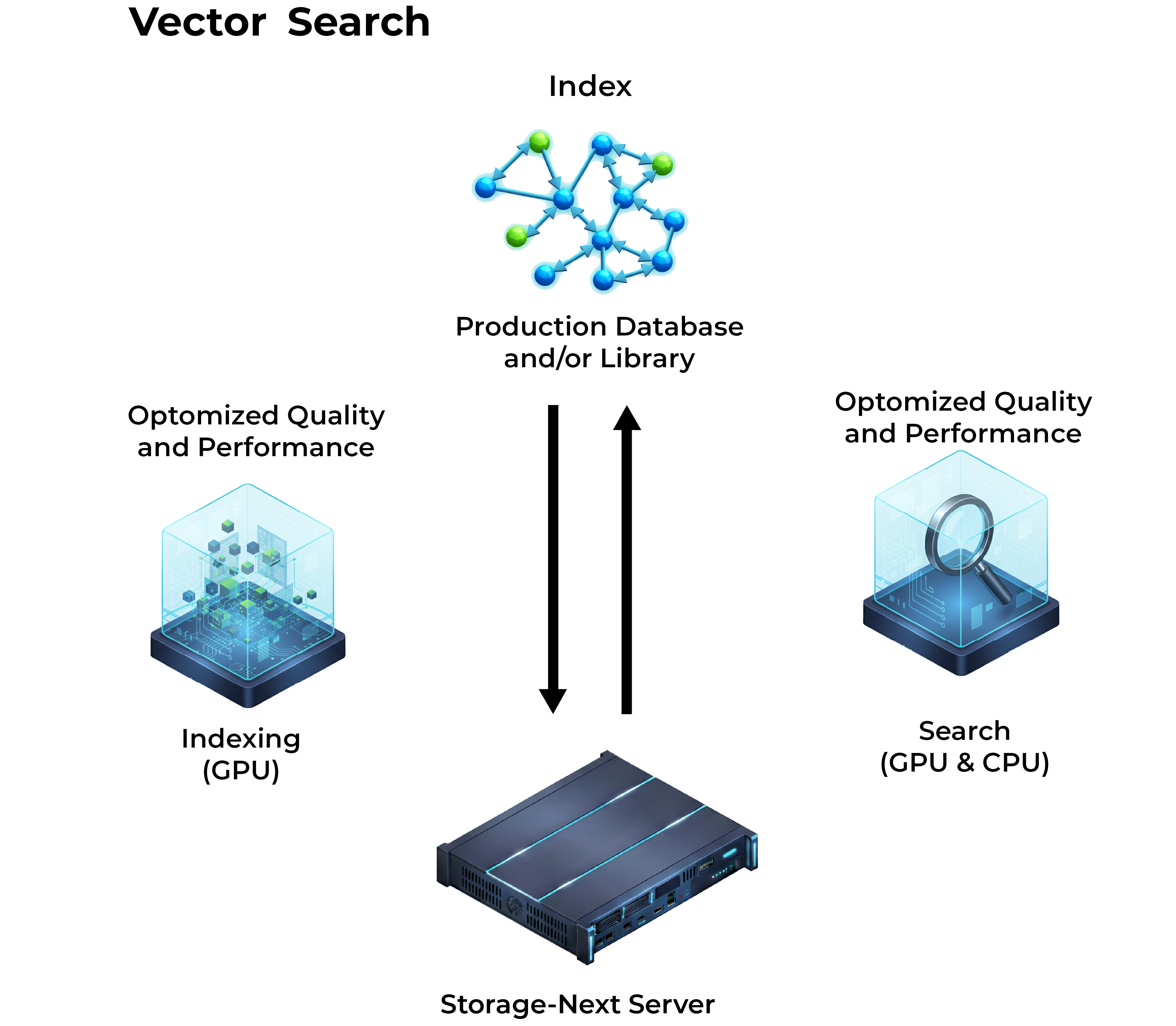
Falcon 6048 is fully optimized for Graph Neural Network (GNN) and vector search workloads, delivering breakthrough performance for graph learning, graph analytics, and large-scale vector database applications. With a GPU-centric architecture, high-concurrency storage subsystem, and native GPU-accelerated indexing, embedding, and retrieval capabilities, Falcon 6048 enables developers to deploy scalable, high-throughput, low-latency AI systems at scale.
| Management Interface | Redfish®, RESTful API, GUI and CLI |
|---|---|
| System Management |
|
| Model Name | Falcon 6048 |
|---|---|
| BMC | Aspeed AST2600 Advanced PCIe Graphics & Remote Management Processor |
| CPU |
|
| PCIe Switch | Two (2) Broadcom PEX 90144 PCIe 6.0 Switches |
| Memory |
|
| NVMe SSD |
|
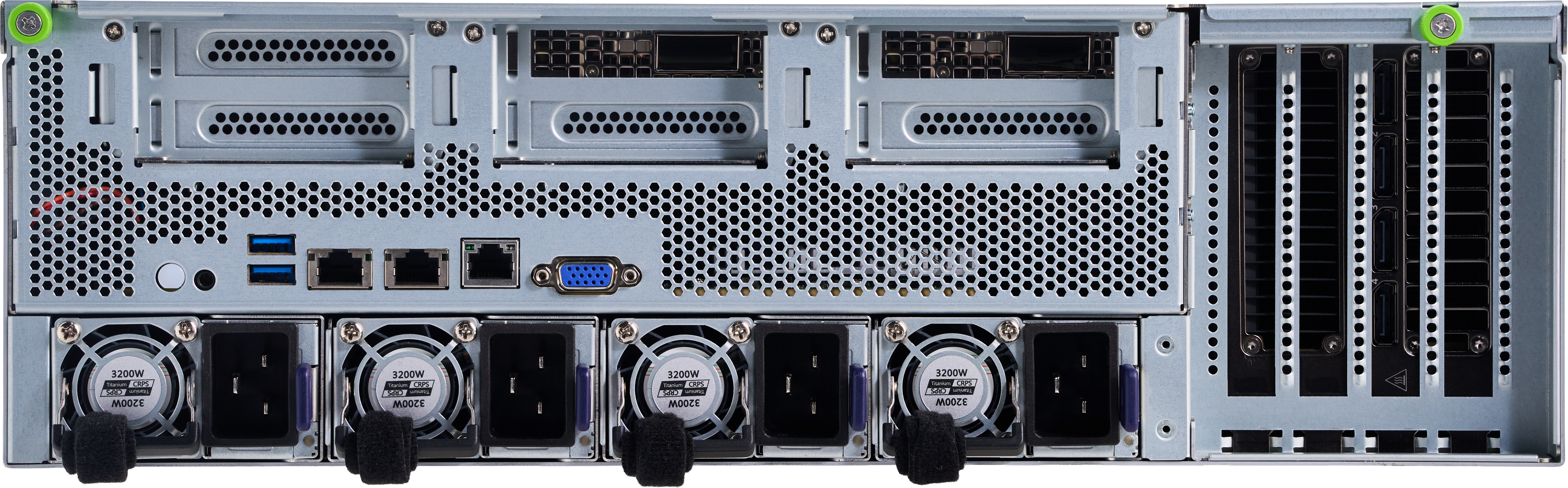
| PCIe Slot |
|
| Power | CRPS 185mm 3200W 80+ Titanium 2+2 |
| Fan |
|
| LAN |
|
| Environmental Spec. |
|
| Dimension | 3U; 129.6 (H) x 438(W) x 850(D) mm |
| Accelerator |
|
|---|---|
| Network Cards | NVIDIA ConnectX-7, ConnectX-8, ConnectX-9 |
With the PCIe 6.0 switch at its core, Falcon 6048 delivers exceptional throughput and scalability. It supports up to 2 NVIDIA H200 GPUs, 4 NVIDIA ConnectX-9 NICs, and 48 NVMe SSDs (depending on available PCIe slots), along with 1 CPU and 8 DDR5 memory modules in the gpu-accelerated server.
This architecture is purpose-built for ultra-high IOPS performance and ultra-low-latency small-granularity data access, enabling efficient processing of massive datasets dominated by small, random I/O patterns—commonly seen in AI training, inference, real-time prediction, and data-intensive workloads.
If you want to apply for any product display, please write a form and we will contact you after receiving the message.